3. PRESENTATION OF THE PLANT
The pilot can see the operation of a solid industrial dryer by convection on a smaller scale. This allows us to study the drying rate of different materials and varying the drying process at different speeds depending on the air and heating powers.
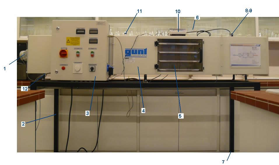
In the next image we see each of the parts of the equipment:
Where:
| 1) Fan |
5) Transparent window |
9) Temperature/ humidity sensor |
| 2) Cuirass |
6) Support material to be dried with frame |
10) Digital balance |
| 3) Control cabinet |
7) Bolt compensation |
11) Temperature T1- humidity sensor  1 1 |
| 4) Drying tube with windows |
8) Anemometer |
12) Heating connection |
The equipment has a size of 2540 x 750 x 1350 mm. The approximate weight is 125 kg. The power supply is 230 V/50-60 Hz / 1 phase.
If we look at each element of the dryer to detail, we see different parts:
• The fan (1)
has a maximum number of revolutions of 950 rpm and a maximum power of removal of 700 m3 / h. It has a power consumption of 33 W and a power consumption of 0.2 A. Always before connecting the fan to the heater. These two are connected to the control cabinet.

From the control cabinet (3) we can see the different values of temperature, relative humidity and air velocity that we obtained as the experiment progresses.
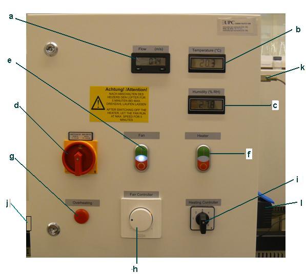
Where:
| a) Air velocity in the drying tube (m/s) |
e) ON/OFF fan switch |
i) Switch to gradual heating power |
| b) Temperature T1/T2 |
f) ON/OFF heater switch |
j) USB connector to record data with the computer |
| c) Relative humidity of air 1/2 |
g) Indicator of overheating |
k) Balance connection |
| d) Principal switch |
h) Control the number of revolutions of the fan |
l)
Base the connector network |
The heater has a power between 500 and 3500 W.
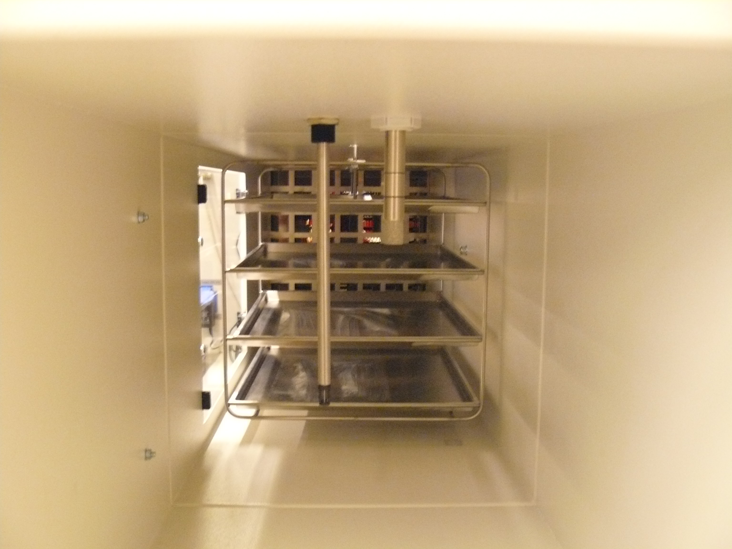
• In the drying channel with window (4) is where the operation of drying the material. The solid material is placed in the trays and you can always look for the transparent cover (5). The trays are placed on supports with a dry material with frame (6) are always placed on the balance (10) to control their weight.
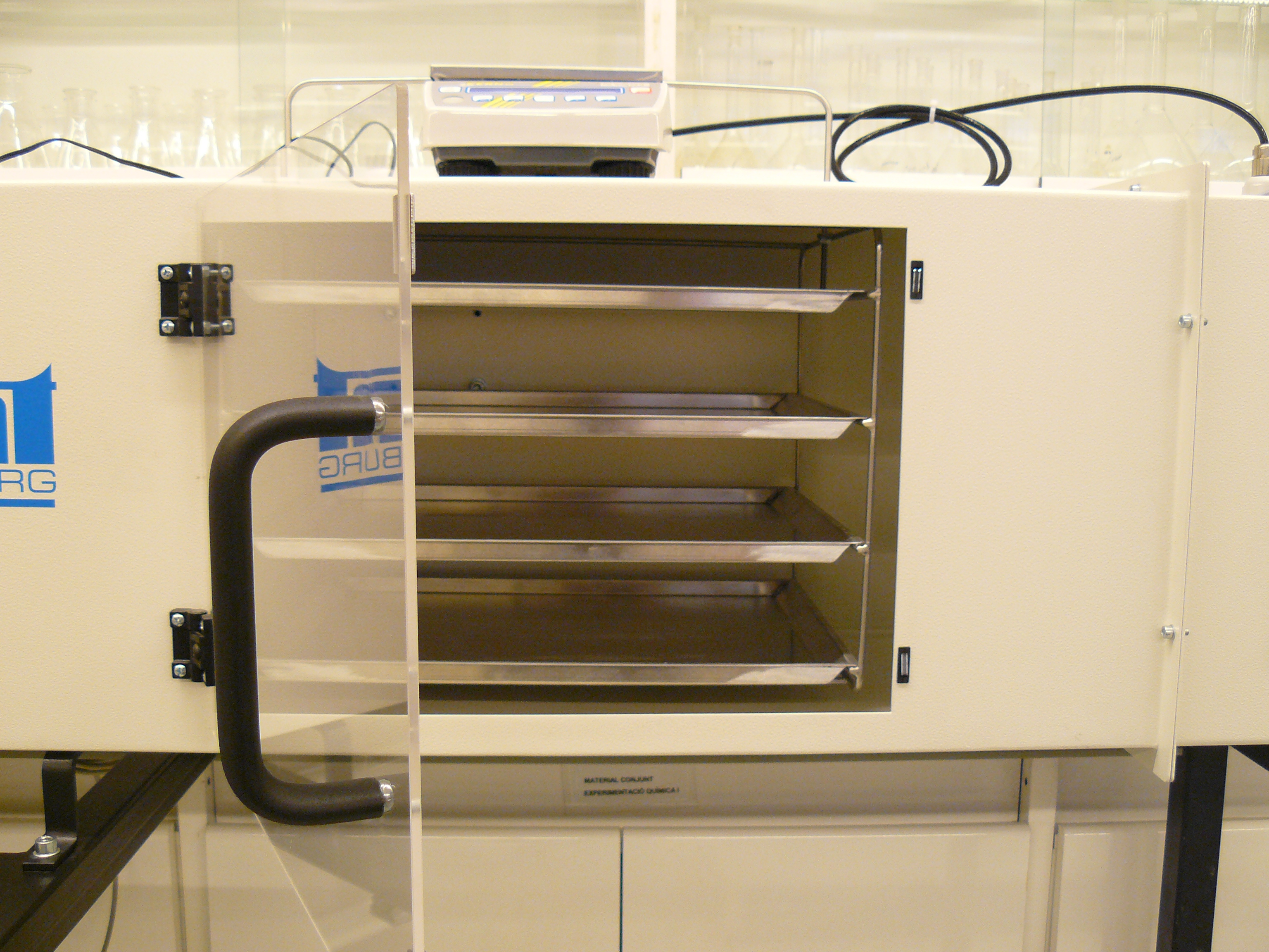
The drying channel (4) has a size of 2540 x 390 x 390 mm and internal dimensions are 350 x 350 mm.
The drying trays have a size of 400 x 300 x 15 mm and in total there are 4 of them. They are made of AlMg3.
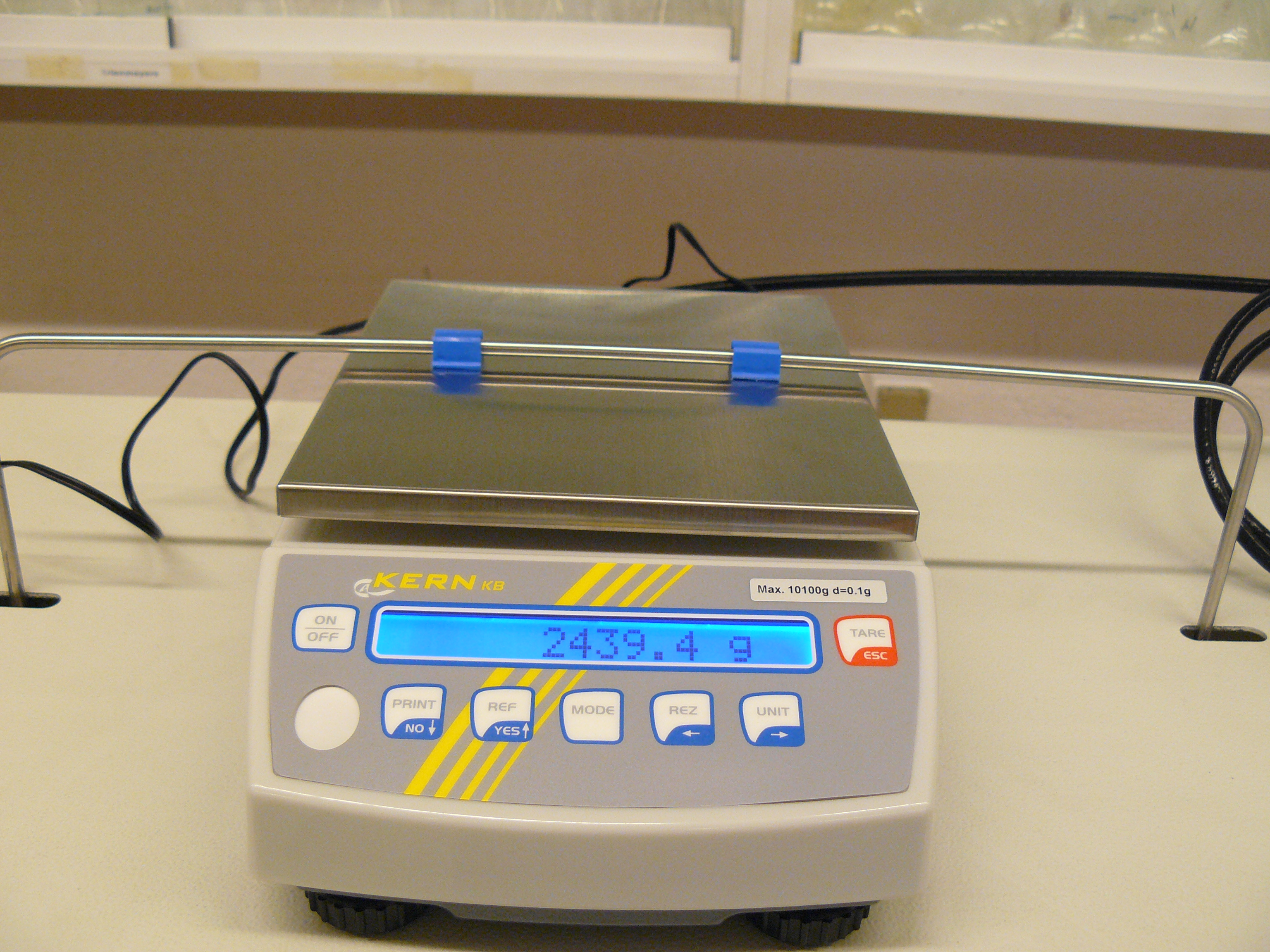
The digital scale (10) has a measurement range from 5 to 8000g. The resolution is 0.1 g. This measures the weight loss experienced by the material to dry during the drying process. The hum balance is directly by a button on the existing balance or through software GUNT CE 130.
• The anemometer (8) measures the air velocity at the end of the drying channel, with a measurement range of 0.2-2.5 m / s. The service temperature of the fluid is -20 to +85 ° C. The measurement accuracy is  (5% of measured value + 0.4% of measurement range).
The temperature and humidity sensor (9 and 11) recorded temperature and relative humidity of the air before and after the material trays to dry. The measured values are displayed in the control cabinet via digital displays. It has a measurement range from 0 to 100% relative humidity. Consider the field of work:
at 23 ºC  2,0%R.H. (40-60%R.H)
at 23 ºC 2,5%R.H. (Left area work)
The following is an image sensor temperature / humidity (right) and the anemometer (left):
In the following video you can see the different parts of the pilot plant: