

In the pilot plant we can see the operation of a small-scale centrifugal pump in industry. This allows us to study the characteristic curves from measuring the differential pressure and flow rate.
In the next picture we can see each of the parts of the device:

Where:
| 1) Water tank. | 4) Manometer (P2). | 7) Diaphragm, pressure sensor and purge valve. |
| 2) Manometer (P1) | 5) Valve. | 8) Flow meter. |
| 3) Pump. | 6) Spherical valve three way | 9) Control Panel |
If we observe each one of the elements of the pump, we can observe differentiate several parts:
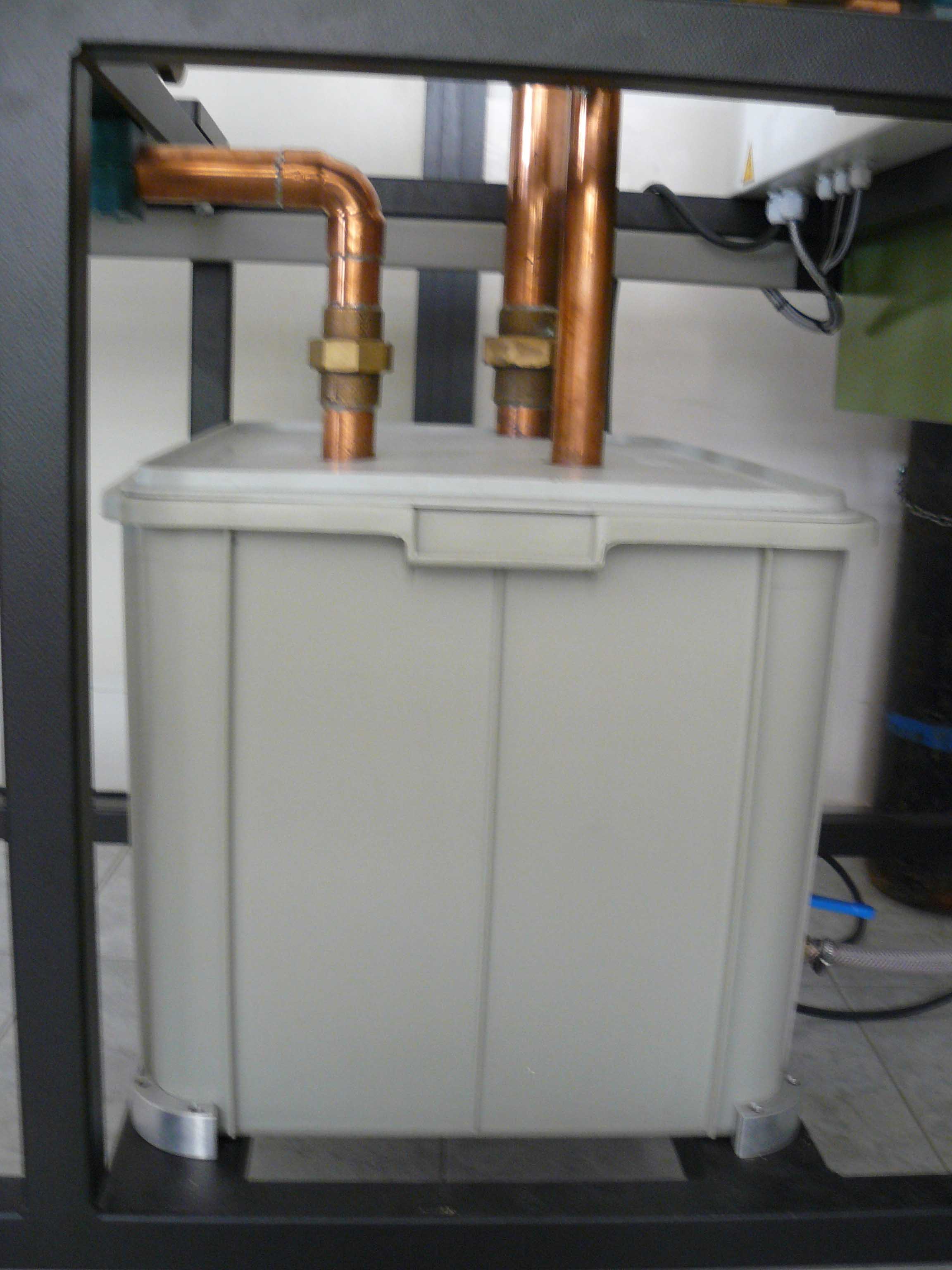
The tank (1) has a capacity of 96 L. It must be checked before starting the experiment that the water level is about 10 cm from the surface.
The standardized pump (3) works with a nominal number of revolutions of 2900 rpm, a maximum lifting height of 22 m and a maximum volumetric flow of 22 m3/h. The roller diameter is 136 mm.

The sensor number of revolutions is below the white cover. This sensor works with a range of 0 to 2,400 rpm. The number of revolutions is activated through the wheel the potentiometer (6)
The tension that feeds the sensor number of revolutions is 10 ... 30V , a maximum charge current of 200 mA and a switching nominal distance of 2 mm.
We must remember that we cannot never vary sharply the number of revolutions, it must be done slowly so not to damage the device.

The alternating current motor that feeds the pilot plant has the following characteristics: nominal power of 1.75 kW, a nominal number of revolutions of 3,435 rpm and a variable frequency FU.

The two manometers (2 and 4) enable us to calculate the differential pressure between two points that are at various heights. The manometer (2) of the band works at a suction pressure (P1) between -1 and +0.6 bar.

The manometer (4) works between 0 and 2.5 bar.

The valve (5) allows us to obstruct the passage of fluid through the plant. When pump is more closer, less fluid circulates for the plant, and differential pressure between the two manometers is higher.

The spherical valve three way (6) allows us to choose whether we want to circulate the fluid to the water meter (position "OFF") or to the diaphragm (position "ON").

The flow meter (8) allows us to measure the total flow. We can determine the volumetric flow through the meter and calculate the time.
We can work with a minimum flow of 0.45 m3/h, a nominal flow of 15 m3/h and a nominal size of 2.

We can also determine the volumetric flow through the diaphragm and the differential pressure sensor (7).
The diaphragm has a diameter of 22.3 mm.

The differential pressure measurement is performed using a sensitive piezo-resistive pressure sensor (I) working from 0 to 500 mbar and the output signal is linear from 0 to 10V
We must remember that to obtain correct measures, we perform a purge of the tube between the diaphragm and the sensor to extract bubbles that may appear. So, we open with the tap of purge (II), we remove the bubbles and re-close.

As we can see in the image, the distribution box (9) marked the values what we obtained in our experiment:
We can distinguish the following parts:

Where:
| a) Emergency stop. | d) Flowmeter (m3/h). | g) Frequency Meter(rpm). |
| b) Wheel. | e) Force Gauge (N). | h) Power Meter(W). |
| c) Button starting / stopping. | f) Dimmer (rpm). |
The following video you can see the different parts of the centrifugal pump industry: