
3. CALCULATION OF CONCENTRIC TUBES HEAT EXCHANGERS
The configuration of the two fluids would be as follows:

With the corresponding graph of temperature distribution:

This proposed the thermal balance equations for each flow: q = W1 · Cp1 · (T1i -T10) q = W2 · Cp2 · (T20 - T2i) * If any fluid has a phase change: q = W· ∆Hphase change (3) Where (in units of the International System (SI)):
|
(1) (2)
(3)
|
Then it raises the general equation of heat pass : q = U0·A0·∆Tlog (if referred to the outer tube inside) (4) q = Ui·Ai·∆Tlog (if referred to the inner tube inside) (5) Where is ∆Tlog: |
(4) (5)
(6)
|
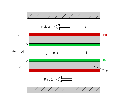
n the picture below you can see the section of a double tube:
|
|
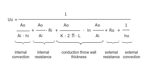
The global coefficient of heat transmission referred to the area outside the inner tube, U0, has the expression:
|
(7) |
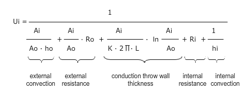
And the coefficient referred to the internal area:
|
(8) |
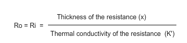
Ri and Ro are the resistances due to fouling occurring inside and outside the inner tube, which hinder the transmission of heat.
|
(9) |
Where: Ao: Area outside the inner tube (m2) Ai: Area inside the inner tube (m2) hi: Convection coefficient inside of the fluid 1 (W/m2K) ho: Convection coefficient outside of the fluid 2 (W/m2K) K: Thermal conductivity of tube material (W/m·K) K' : Thermal conductivity of the resistance (W/m·K) L: Pipe length (m) Ro: resistance due to fouling of the outer fluid 2 (m2K/W) Ri: internal resistance due to fouling of the fluid 1 (m2K/W) X: Thickness of the resistance (m) |