3. CALCULATION OF CONCENTRIC TUBES HEAT EXCHANGERS
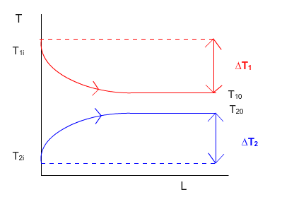
3.5. DIAGRAMS OF TEMPERATURE DISTRIBUTION
The thermal balance equations are:
q = W1 · Cp1 · (T1i -T10) = C1·∆T1
q = W2 · Cp2 · (T20 - T2i) = C2·∆T2
Where (in units of International System (SI)):
q = heat a fluid that is transmitted to another (J/s)
W1 = mass flow of hot fluid (1) (Kg/s)
W2 = mass flow of cold fluid (2) (Kg/s)
Cp1= heat capacity of the hot fluid (1) (J/Kg·K)
Cp2 = heat capacity of the cold fluid (2) (J/Kg·K)
T1i= initial temperature of the hot fluid (1) (K)
T10 = final temperature of the hot fluid (1) (K)
T 2i = initial temperature of the cold fluid (2) (K)
T20 = final temperature of the cold fluid (2) (K)
Where C1 and C2 are heat capacities total:
C1= W1 · Cp1
C2= W2 · Cp2
|
(1)
(2)
(11)
(12)
|
If the equations (1) and (2) are equal :

|
(13) |
COUNTER CONFIGURATION
- If C1 > C2 then ∆T1< ∆T2

- If C1 < C2 then ∆T1> ∆T2

- If C1 = C2 then ∆T1= ∆T2
PARALLEL CONFIGURATION
- If C1 > C2 then ∆T1< ∆T2
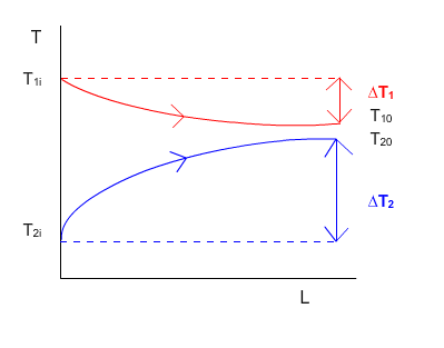
- If C1 < C2 then ∆T1> ∆T2
- If C1 = C2 then ∆T1= ∆T2