


4. GENERAL METHODS OF CALCULATION OF HEAT EXCHANGERS
4.2. Method ε-NTU
4.2.1. Graphs of method ε-NTU for different equipment
The following are the graphs of the E-NTU method for different equipment or different configurations (η = ε, i NT = NTU ):
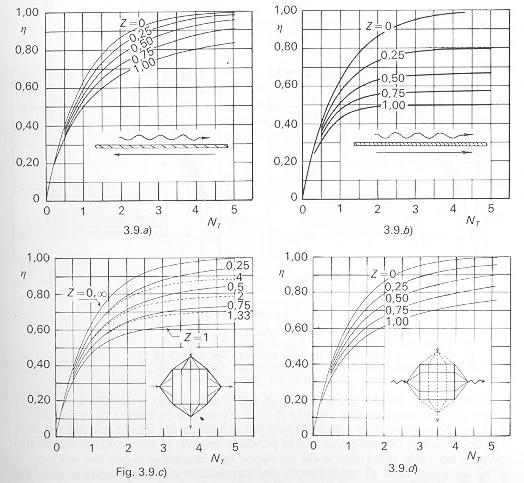
a) Heat exchanger 1-1 (counter).
b) Heat exchanger 1-1 (parallel).
c) Cross flow heat exchanger multitube 1-1. Fluid external mixed.
d) Cross flow heat exchanger multitube 1-1. Both fluids without mixing.
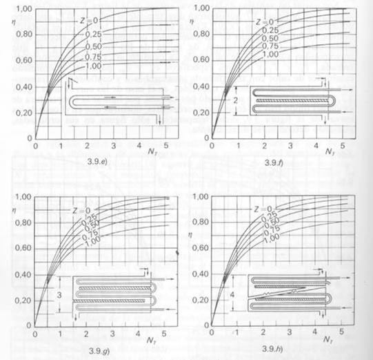
e) Heat exchanger multitube 1-2, 1-4, 1-6,...
f) Heat exchanger multitube 2-4, 2-8, 2-12,...
g) Heat exchanger multitube 3-6, 3-12, 3-18,...
h) Heat exchanger multitube 4-8, 4-16, 4-24,...