

3. PILOT PLANT ABSORPTION OF GASES
3.1. Main parts of the pilot plant
3.1.4 Column
In the column, not only must take into account the column, but there is also the part of the filling, the sampling points, the silencer, the pressure regulating valve, the separator of water, among other items.
The figure below shows the most important elements that are linked to the column.

Figure 3.17: Absorption column.
1- Point sampling at the exit of the column (Point 3).
2- Fillings.
3- Pressure control valve of the column.
4- Point sampling in the middle of the column (Point 2).
5- Top of the column.
6- Silencer.
FILLING COLUMN
Of filling there are many shapes and sizes. Be placed in an orderly manner, if the volume of the filler is large (5-20cm) or disordered if the filling volume is small (5-50mm). What usually used in industries are large Rasching rings 5-8cm in diameter and placed in an orderly manner.
This column is used rings Rasching, and are placed randomly, it means they have small dimensions.
The characteristics of the filling are:
- Must be chemically inert.
- Must have a high degree of mechanical strength.
- They allow the passage of the two currents appropriate.
- They allow good contact between the two phases.
- Must be low cost.
Most fillings are made of cheap materials, light and inert. Such as clay, graphite, porcelain, plastic ... the backfilling of the pilot plant are plastic. You can use both the regular and irregular shapes.
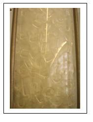
Figure 3.18: Column filling.
PART UPPER OF THE COLUMN
As shown in the figure entrance of the water is to the top of the column. This water is boosted with water pump which is located at the bottom of the device. The water falls into the column so that it mixes with the air entering the bottom. The contact is counter current and thus we get a greater contact of the two phases. The function of the filling is to provide a greater contact surface between the two phases, and get a better separation.
At the top we find out exit the air when this air is clean of CO2.
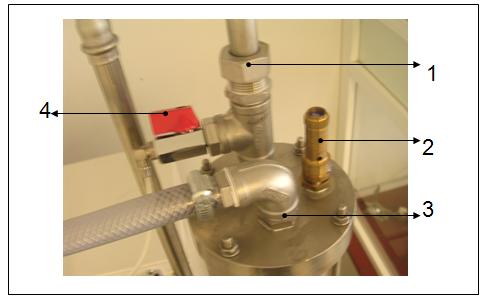
Figure 3.19: Top of the column.
1- Out of air.
2- Leaving purge pressure.
3- Check the water column.
4- Tap step pressure at the top of the column.
DISTRIBUTOR OF WATER
The distributor the water is located within column, at the top as shown in figure 3.20.
The objective of this instrument is disperse the water throughout column, so provide a good contact between the gas phase (air mixed with CO2) and the liquid phase by filling, which provides a larger contact area.

Figure 3.20: Water dispenser.
CO2 AND AIR FILTER
As can be seen in the figure below this filter is present inside the column at the bottom. This has a certain porosity to allow passage of air and carbon dioxide, but not possible particles that can drag the gas.
The goal is to filter out particles that could enter with air into the column and could bung exit out of the air column.

Figure 3.21: Filter within the column.
WATER SEPARATOR:
The water separator is located at the rear of the column. Used to separate the water that leaves the sampling point 2 (middle column), since due to the pressure and flow of water at this point, the water comes out instantly. The measuring device Oxybaby used to measure how much is carbon dioxide in the column, this can not be wet, because if it gets wet then gives erroneous results and also can be damaged. For this reason it is necessary to use the water separator.
The connection of this device is important. Must connect a plastic tube from the point of the middle column until the entrance of the separator. The filtered water is instantaneous, which makes the air mixed with CO2 exit to the other end of the separator. At the exit, you need to connect another plastic tube or rubber to make reading the Oxybaby as shown in Figure 3.22.

Figure 3.22: Water separator.
1- Sample tube connecting the middle point of the column with water separator.
2- Check the air when excess CO2 and water separator.
3- Deposit of the water separator.
4 -Tube where air and CO2 comes to reading the percentage of CO2.
5- Wheel to empty.
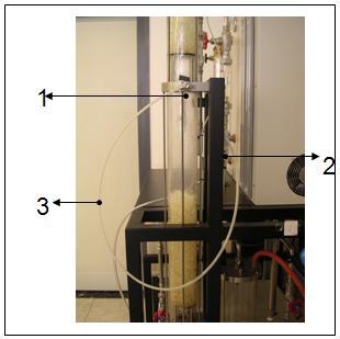
Figure 3.23: Connecting the water separator to the point of measurement.
1- Point of measurement.
2- Water separator.
3- Tube connection.
SILENCER
As its name say, the silencer is used to reduce the noise made by the to go outside the column.
This device is located at the end of the process, the output of the air, where there is screwed.
The main problem of this is losing water. As the water circulates inside the column absorption reaches a temperature of approximately 26 to 30°C, water is lost for the silencer. This lost water is moist air inside the column, which get in contact with the temperature outside is compressed and causes the steam becomes liquid water.
Therefore, we bear in mind that this device is water loss, but not significant amounts. Therefore these losses do not affect the values obtained.
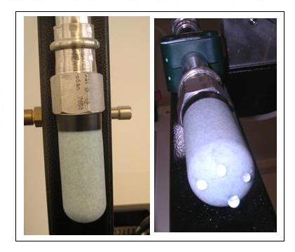
Figure 3.24: Silencer.
The properties of the water separator are:
- Length x width x height: 67x78x23, 5mm
- Material: plastic SEK.
- Weight: 10.8 g.
PRESSURE REGULATIONG VALVE:
The pressure regulating valve of the column is located in the central part of the team, next to the column. This serves to regulate the pressure inside the column. This pressure is controlled by pressure on a manometer, which was previously mentioned.
This valve works so that you have to turn to the right if you want to reduce the total pressure in the column, or turn to the left if you want to increase the pressure. With small movements can produce large changes. So when it comes to regulating the pressure must be careful not to go over the limit for the device (1 bar).
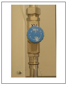
Figure 3.25: Valve regulating the pressure of the column.
SAMPLING POINT
In column are located two points for catch samples, as shown in figure 3.26.
The sample points are used to measure how much carbon dioxide it absorbs water. To measure the amount of CO2 that is absorbed we are used the digestive Oxybaby, with units of percentage.
These taps should be opened little, because if you open a lot, pressure within the same column ago that the water comes out and reading to be erroneous Oxybaby.
The point marked with number two in the figure is that the figure belongs to point 2, which measures the amount of carbon dioxide absorbed in the water at the bottom of the column. The point marked with number 1 is that he belongs in the paragraph 3, which measures the amount of carbon dioxide absorbed over the top to the bottom of the column.
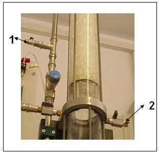
Figure 3.26: Point of hurry sample.
1- Point of hurry sample POINT 1. (output column).
2- Point of hurry sample POINT 2. (middle column).