

3. PILOT PLANT ABSORPTION
3.1. Main parts of the pilot plant
3.1.5 Lower part of the team
At the bottom of the device is where you find two tank, two pumps and their corresponding valves. The figure shows how this whole mechanism is located:

Figure 3.27: Bottom of the device (1).
1- Bottom of the column.
2- Pressure gauge.
3- Air filter and carbon dioxide.
4- Luggage Depression.
5- Valve into the tank of depressions.
6- Water tank.
7- Bomb 2 depression.
8- Faucet pressure control at the bottom of the column.
9- Water recirculation tube.
10- Tap water purge.
11- Valve regulating the level of the column.
12- Pump 1 (pumping water).
13- Vent the reservoir pressure of depression.
14- Valve pressure.
15- Valve regulated.
16- Thermometer.
17- Sample point (point 1).

Figure 3.28: Bottom of the device (2).
This section of the device, the mechanism serves to make basically the cleaning of CO2 from the water.
RESERVE WATER TANK:
Initially, in the deposit it should make tap water: water clean. Clean water means there is little presence of carbon dioxide. Importantly, the tap water present carbonate ions, but are in very small numbers, so you can still absorb more CO2.
Carbon dioxide produce a change of pH in water, which pass the neutral pH of 7 to a pH of about 5.5 or lower. Carbon dioxide is slightly dissolved in water and forms a weak acid, which is called carbonic acid (H2CO3), according to the following reaction:
![]()
This carbonic acid formed reacts irreversibly and gently with water and formed a hydronym cation (H3O+) and bicarbonate ion (HCO3-) as shown in the following reaction:
![]()
This tank is where the pump 1 drives the water into column, the water go out the column, passes through the tube and water circulation is returned to the tank a bit more dirty in terms of CO2 content in water because the water has absorbed a certain quantity of CO2.
The main characteristics of the water tank are the following:
- Length x width x height: 660 x 450 x 220mm.
- Material: Polyethylene (HDPE).
- Volume: 50 L

Figure 3.29: Water tank.
PURGE OF WATER:
The water purge is carried from the tap shown in the figure below. Serves to empty the reservoir and to take samples to analyze the water content of carbonates present. We must analyze the water and can be done by three different methods to see if it is saturated with carbon dioxide.
The three methods of water analysis are:
- Measure the pH.
- Determination of carbonates, from a rating with NaOH.
- Test Kh.
These methods are detailed in section 3.2.
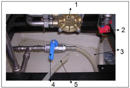
Figure 3.30: Tap water purged.
1- Water pump 1.
2- Tap of the water purge in column.
3- Tank to collect water.
4- Tap purge water reservoir.
5- Rubber tube.
WATER AND DEPRESSION PUMPS:
The two pumps are centrifugal pumps which are located on the right side and bottom of the device.
A centrifugal pump is a type of hydraulic pump that transforms the mechanical energy of a rotating impeller in potential and kinetic energy. The fluid enters the centre of the roll, which boasts axis to drive the fluid, and the effect of centrifugal force is pushed outside, where it is picked up by the casing or pump body.
Although the centrifugal force produced depends both on the periphery of the speed of the impeller as the density of the liquid, the energy applied per unit mass of liquid is independent of the density of the liquid. Therefore, since the pump operates at a certain speed and use a defined volume of fluid, the energy applied and transferred to liquid (in liquid pie-lb/lb) is the same in any liquid without import its density.
The majority of these bombs is application in the world of industry because they are suitable for many services. The most common are built according to DIN 24255 standards, which have a roller and have a capacity up to 500m3 /h and they arrive to drive up to an altitude of 100m. These are usually mounted horizontally, but can also go vertically.
These types of pumps have a flow that is uniform and are free of low frequency pulses, which causes that do not have valves.
The main features of the two pumps are:
- Type: centrifugal pumps.
- Power: 0.25 kW.
- Number of revolutions per minute: 2800 rpm.
- Transport maximum flow: 18 L / min.
- Maximum lifting height: 50m.
- Material: brass.

Figure 3.31: Water and depression pumps.
1 - Pump 2: depression.
2 - Pump 1: drive water .
Pump 1: drive water :
This pump is located in front of two more bombs. This will come into operation whenever you wish to spend the water in column. So to make it work is necessary to pulse the double push of a distribution box.
The main objective is to supply water to the tank column, by pumping from a pump 1.

Figure 3.32: Pump 1 for drive water.
Pump 2: depression:
This pump is what lies behind most of the two bombs. Into operation only when the process wants to clean up CO2 of the water.
The purpose of the pump is to provide enough pressure to extract carbon dioxide from the water. EI transport of gases is produced outside of the tank.

Figure 3.33: Pump 2 of depression.
DEPOSIT OF DEPRESSION AND DEPRESSION MANOMETER.
Located at the rear and its function is to clean the water carbon dioxide.
Having reached saturation point, water does not absorb more CO2 .In order to continue using the water must be cleaned to remove carbon dioxide are present. This is achieved by placing depression tank. This comprises a tube of glass with two stainless steel flanges, where the depression in the deposit is generated from jet pump water pump 2 depression. The pressure present inside the tank is controlled to give birth to a manometer depression, as shown in the figure below:

Figure 3.34: Deposit of depression and depression manometer.
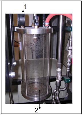
Figure 3.35: Deposit of depression.
1- Depression manometer.
2- Deposit of depression.
Due to the depression that's inside the tank, water is transported from the reservoir tank to depression tank through the inlet valve to tank of depression.
The process of depression of the water can be made both during and after absorption.
PRESSURE VALVE AND REGULATING VALVE.
On the right side of the deposit of depression are two valves that located to carry out the theme of clean carbon dioxide from the water.
The regulating valve is responsible for regulating the level of water that goes to the second pump (pump depression).
The pressure valve serves to regulate the pressure inside the tank of depression, so that from the gauge that is located above the tank can be regulated so comfortable you will want to have the pressure inside the deposit.

Figure 3.36: Pressure valve and regulating valve.
1- Valve regulation.
2- Pressure valves.
3- Deposit depression.
VALVE OF ASPIRATION TO DEPRESSION DEPOSIT AND ADJUSTMENT VALVE OF THE LEVEL OF THE COLUMN.
The two valves used to regulate a specific function. The valve to the tank of depression is used in the process of cleaning carbon dioxide from the water.
You must open the valve a little and will be responsible for transporting water to the reservoir tank of depression, as long as the supply of water to the pump is opened and the valve of pressure pump 2 is closed.
The adjustment valve of the level of the column is responsible, together with the adjustment valve on the pressure of the column to maintain an optimal level of water at the bottom of the column. To close the valve we turn it clockwise to open it and flip it left. Movements must be very mild, as with minimal movement, striking changes in the level.
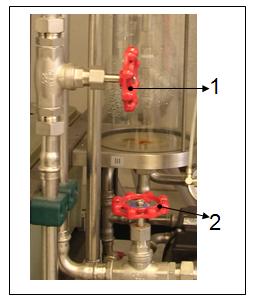
Figure 3.37: Valve of aspiration to depression deposit and adjustment valve of the level of the column.
1- Valve of aspiration to the tank of depression.
2- Adjustment Valve level of the column.
SAMPLING POINT.
In the following figure can be seen where is located the sampling point is how to measure the amount of carbon dioxide that is present at the entrance of the column. It is the name POINT 1.

Figure 3.38: Sampling point (POINT 1).
WATER SUPPLY.
The water supply used to operate the pump 2 in the cleaning process of water in carbon dioxide.
Therefore, the first step that is required to initiate the process is cleaning it open a little supply that is located behind the device stuck to the wall. This water will be regulated through the regulating valve, located at the bottom of the device.

Figure 3.39: Water supply.