

3. PILOT PLANT ABSORPTION OF GASES
3.1. Main parts of the pilot plant
3.1.6. Supply of CO2
The main objective of the pilot plant is to absorb carbon dioxide from tap water that comes from the reservoir. In the case of carbon dioxide comes from the cylinder of CO2 .
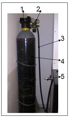
Figure 3.40: Supply of CO2.
1- Valve opening and closing.
2- Gauges of CO2.
3- Tube CO2 carrier.
4- Cylinder of carbon dioxide.
5- Point of sampling.
PHYSICAL AND CHEMICAL PROPERTIESOF CARBON DIOXIDE
Carbon dioxide may be in gaseous state, liquid or solid. It is a central carbon atom, together with two double bonds to two oxygen atoms (CO2). Its alignment is straight (O = C = O). The properties in the case that is in gaseous state: is a colourless, odorless, where its density is 1.97 g/l (at 0 º C and 1 atm.) And is very reactive. If it is in a liquid state: colourless, odorless, volatile, where the density varies to 1.01 g/l (-37 ° C). If it is solid (dry ice) is white where the density is 1.56 g/l (-79 º C) the melting point of -78.5 ° C (sublimates).
All forms of carbon dioxide are non combustible and very miscibles with water, but also is miscible with hydrocarbons and most organic liquids.
It is a suffocating gas concentrations at 10% or more, but the concentrations are low pulmonary ventilation (1-3%).
It is a by product of the fermentation of carbohydrates and a final product of combustion and respiration.
In the air there is 0.033% CO2 which promotes the formation of the greenhouse effect.
The dangers that can cause carbon dioxide are: in solid carbon dioxide harms the skin and tissues and in a gas form in high concentrations can asphyxiate people.
Their utilities are: refrigeration, carbonated drinks, the aerosol propellant, intermediate chemical, low temperature tester, fire extinguisher, inert atmospheres, medical, municipal water treatment, enrichment of air in greenhouses.
Its properties are shown in the following table:
Table 3.1: Physical and chemical properties of CO2 .
Molecular shape |
CO2 |
Molecular mass |
44,01g/mol |
Molecular shape |
Lineal |
Crystal structure |
Type of quartz |
Dipole moment |
Zero |
Solid state |
Dry Ice |
Appearance |
Gas or solid |
Gas colour |
Colorless |
Solid color |
White |
Number CAS |
124-38-9 |
Solid phase density |
1600kg/m3 |
Gas phase density |
1,98kg/ m3 (temp. de 298K) |
Solubility in water |
1,45kg/ m3 |
Melting Point |
- 57ºC (216K) |
Boiling Point |
-78ºC (195K) |
Latent heat vaporization |
25,13 kJ/mol ( 1atm) |
Viscosity |
0,07 cP a -78ºC |
Acidity |
6,35 and 10,33 (pKa) |
Thermal conductivity |
16,65 mW(1atm and 0ºC) |
CYLINDER OF CO2
The carbon dioxide cylinder is located on the left side of the device, next to the wall.
The cylinders containing compressed gases at extremely high pressures should be used with some caution. The cylinders used to compress large amounts of gases in confined spaces, such as oxygen, acetylene, carbon dioxide .... may present risks of physical or chemical types. When this gases mix with air may form flammable and explosive mixtures (chemical hazards). The cylinders have valves and regulators that control the output of gases.
Exposure to toxic gases or asphyxiation due to lack of oxygen is released as gas in an enclosed, can be a high health risk.
It is important that the worker who is in contact is informed about: how to identify the contents of the cylinder, what is the proper handling, use appropriate EPI according to the gas used.
Regarding the storage must be remembered that: are to avoid the blows, be tying individual, with strings at a height of 2 / 3 of the cylinder in a secure wall. Be stored in well-ventilated areas away from flammable materials. They empty bottles, must be saved separate to those who are full, and mark them as empty.
To avoid damage or break the main valve must always put the protection cap on the bottle is not in use.
When you are in poor condition, the contents of the internal pressure can be released violently, because the valve fails or the cylinder may be perforated. This output can drive the gas cylinder pressure at ground level to 50 km / h and altitude up to 1200m. The energy released can also cause the cylinder to turn, bounce or even pass through walls. The release of the pressure cylinder can be a serious physical threat.

Figure 3.41: Supply of CO2.

Figure 3.42: Top of the cylinder of CO2.
1- Valve opening and closing.
2- Gauges of CO2.
3 - Tube CO2 carrier.
4 - Cylinder of carbon dioxide.
The characteristics of the label of the CO2cylinder.
- Content asphyxiating gas in high consultations.
- Store in a well ventilated place.
- Do not breathe gas.
- Avoid shock and protect the container from the heat source.
- Open the valve slowly.
- Avoid all back into the bottle.
MANOMETER OF CO2
At the figure 3.43 can be observed in the gas bottles are two pressure gauges to regulate gas pressure.
These pressure gauges indicate the amount of gas that is inside the cylinder.
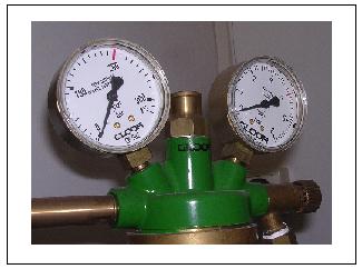
Figure 3.43: Manometers of CO2(1) .
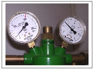
Figure 3.44: Manometers of CO2(2).
The figure 3.43 shows that the pressure gauges indicate when the CO2 cylinder is empty. Then when to withdraw it there and change it to a new one.
Initially the figure 3.44, the cylinder are closed and you can be observed that the first manometer mark approximately zero. Instead the second manometer mark approximately 1.5 bar. We observed in the second rubber of the manometer is that the needle is not dilated and not works well, therefore, must make a change of manometer.
Before changing the manometer will continue until you pass various tests observed in figure 3.45.

Figure 3.45: Manometer of CO2(3).
This figure shows that the manometer pressure cylinder of carbon dioxide is frozen, it is because the tube connecting the gas to the device loses carbon dioxide, which to get in contact the manometer, and therefore the temperature outside was freezing slowly. So the board should be changed to another stainless steel copper.
POINT CO2 CALIBRATION FOR OXYBABY
The figure 3.46 shows the connection of the apparatus with carbon dioxide, so it can be seen that a sampling point covered by the tap of the output regulation of CO2.
Carbon dioxide is transported from the cylinder inside the device through a tube of black rubber, the number 2 from the figure, once entered into the pilot plant, carbon dioxide is mixed in point of mixing with the air coming from the compressor.
The sampling point of the CO2 used to calibrate the device for measuring carbon dioxide Oxybaby, since this point marks the 100% carbon dioxide.

Figure 3.46: Sampling point of CO2.
1- Point sampling of CO2.
2- Rubber hose, CO2 carrier.
3- Regulating tap.
To see parts of the pilot plant, see the following video: