

4. EXPERIMENTAL PROCEDURE
4.4. Practice 2: Loss pressure with water and air
Introduction
The aim of this practice is to measure pressure losses that have the pilot plant, from the operation from to the compressor and water pump.
Pressure losses, also called energy loss is dynamics energy loss of fluid due to friction between the particles of the fluid itself and against the walls of the pipe containing the fluid. The losses may be continuous along the pipe, or localized. Everything depends on the particular circumstances, such as a narrowing, a change of direction, the presence of a valve, etc.
These can occur in any industrial plant in this case, we want to explore that occur in a gas absorption tower. This technique serves to isolate a liquid through a gas. In exactly this device consists of a mixture of air with carbon dioxide and liquid extractor is water.
The loss of pressure inside the column are measured with two manometers tubular U-shaped, so that these gauges indicate the pressure differential. dp1 is the pressure difference between the top of the column to the centre of the column. And dp2 is the pressure difference that occurs between the bottom of the column and the central part. To measure the total pressure must be the sum of pressure differences:
![]()
Mainly students must have clear what parts of the pilot and what does each instrument and valve operation. We can help from the following schemes:

Figure 4.21: Distribution box and situation of the valve adjustment level.
1- Emergency switch.
2- Main switch.
3- Valve Adjustment level of capacity of the column.
4- Double push the compressor.
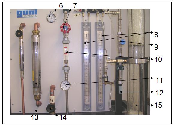
Figure 4.22: Panel elements.
5- Bourdon type manometer.
6- Valve adjustment of water.
7- U-shaped tube manometer
8- Valve adjustment pressure column.
9- Flow meter water.
10- Thermometer water.
11- Muffler, exhaust air.
12- Air flow meter.
13- Air valve adjustment.
14 - Column filler.
Material
Pilot plant absorption of gases.
Procedure
First, we must turn the device:
- Open the main switch (2) (make sure that the emergency switch (1) is not actuated).
- Close the valve adjustment for level of ability in column (3).
- Open the valve completely by adjusting the air flow (13) and the pressure adjustment valve (8).
- Set up the push button dual compressor (four) and adjust the airflow, the air valve adjustment (13).
Already we can begin to make the practice:
-Ensure that the water flow is 75 l/h, but must fit with the water valve adjustment (7).
- Then you must regulate the airflow at 30 l/min through the air regulating valve (14).
- Observe the pressure losses that occur in the U-shaped tubular pressure gauges, increasing the air flow of 10 l/min increasing to a maximum flow of 60 l/min.
- In order to control the pressure to turn gently pressure control valve of the column (9) to control the volume of air must rotate smoothly valve adjustment of airflow (14 ). Should move fairly synchronized, because if they move independently, the first one and then another, keeping the water level in the bottom of the column is much more difficult.
- In order to maintain the level of water in the bottom of the column should be: First regular 75 l/min of water with 30 l/min of air at a relative pressure of 0.5 bars , from the valve adjustment level of the column (3.) Once these parameters adjusted to maintain the level of the column will be easier to do it from the valve adjustment pressure column (9.)
- It is very important that the water level there has to be within the column should be constant, since access to water causes an increase in pressure losses and a decrease in pressure on the column .
- Write down all the differences of pressure in the following table:
Table 7.3: Loss of pressure in the column.
Gair (l/min) |
dp1 |
dp2 |
dp |
dp1 |
dp2 |
dp |
dp1 |
dp2 |
dp |
dp (average) |
30 |
|
|
|
|
|
|
|
|
|
|
40 |
|
|
|
|
|
|
|
|
|
|
50 |
|
|
|
|
|
|
|
|
|
|
60 |
|
|
|
|
|
|
|
|
|
|
Where dp1, dp2 and dp are mmH2O.
- Once performed all the tests at a desired water flow of 75 l / h, must pass out the following volumes: 100, 150 and 200 l / h. Always following the same procedure described above.
- Once the practice completed, disconnect button a pump 1(5) and expect that all the water downs inside the column.
- Disconnect the compressor with double push button (4) located in the box.
- Disconnect all of the installation with the main switch (2).
The following video you can see how this is done in practice:
Questions
1) Why the loss of pressure occur?
2) What is a column filler? And the plates?
3) Why serve the rotameters?
4) Fill the table for each body of water to 75,100,150 i 200 l/h:
Table 7.4: Pressure losses in column.
Gair (l/min) |
dp1 |
dp2 |
dp |
dp1 |
dp2 |
dp |
dp1 |
dp2 |
dp |
dp (Average) |
30 |
|
|
|
|
|
|
|
|
|
|
40 |
|
|
|
|
|
|
|
|
|
|
50 |
|
|
|
|
|
|
|
|
|
|
60 |
|
|
|
|
|
|
|
|
|
|
Where dp1, dp2 and dp are mmH2O.
5) Represent the loss of pressure on a graphics.
6) What differences can be observed between the experience made at 75,100,150 and 200 l /h?
7) Expresses the loss of pressure in different units and fill the table.
Taula 7.5: Loss of pressure in different units.
G(l/min) |
dp (mmH2O) |
dp (atm) |
dp (bar) |
dp (Pa) |
dp (mmHg) |
dp (Kg/cm2) |
30 |
|
|
|
|
|
|
40 |
|
|
|
|
|
|
50 |
|
|
|
|
|
|
60 |
|
|
|
|
|
|
8) Discuss the results.